Although sphere mapping is generally convincing, it is not generally correct. Most of the artifacts come from the fact that the sphere map is generated at a single point and then applied over a large number of points. Objects with interreflections cannot be handled correctly. If reflected objects are close to the reflective object, their reflections should appear differently when viewed from different points on the reflector. Using sphere maps, this will not happen. Sphere mapping results are only correct if you assume that all the reflective objects are infinitely far from the reflective object.

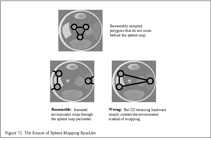
Interpolation of the texture coordinates also leads to artifacts. Texture coordinates are computed at the vertices and linearly interpolated across the polygon. Unfortunately, the sphere map is not in a linear space, so this interpolation is not correct. Additionally, the linear interpolation will not take into account the fact that the points at the edge of the circle all map to the same location. Coordinates may be interpolated within the circle of the sphere map when they should be interpolated across the boundary [101]. Figure 72 shows how this occurs.

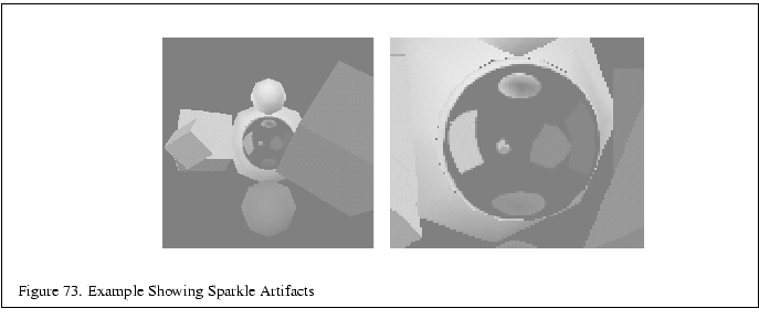
This is responsible for an unsightly artifact that appears as random ``sparkles'' or ``dirt'' at the silhouette edge of a sphere mapped object. As long as the sphere map center reflects directly back at the viewer and reasonable vertex normals are supplied, the artifacts are only a problem at the silhouette or grazing edges of objects because that is where vertex normals of a polygon are likely to cause wrapping to the other side of the sphere map. Because these grazing polygons are small in screen space, the number of affected pixels is usually small. Still the effectively random sparkling can be objectionable, particularly in animated scenes. Figure 73 shows a scene and a zoomed version of the scene showing sparkles at the silhouette edge of the sphere mapped object.
The final major limitation of sphere maps is that their construction assumes that the center of the sphere map is what reflects directly back at the viewer. Recall that in the discussion about the construction of sphere maps, both by ray casting or by texture warping, the construction involves a particular view orientation. The sphere map image is said to be view dependent. This means unless the sphere map is regenerated for different views, the sphere map will be incorrect.
It is possible using the six cube map views to continuously re-warp a new sphere map texture for different views. If the environment mapped object is to reflect a dynamic environment, this continuous re-warping is required anyway. This ends up being a major limitation for using sphere map in complex dynamic scenes with a continuously changing viewer.