In [39,40] lighting and shading algorithms are developed based on traditional technical illustration practices. A non-photorealistic lighting model for matte and metal surfaces is constructed. The model for matte surfaces use both luminance and hue changes to indicate surface orientation. This lighting model reduces the dynamic range of the luminance, reserving luminance extremes to emphasize edges and highlights. To compensate for the reduced dynamic range and provide additional shape cues, tone-based shading adds hue shifts to the lighting model. Exploiting the relationship that cool colors (blue, violet, green) recede and warm colors (red, orange, yellow) advance, a sense of depth is added by including cool to warm color transitions in the model. The diffuse cosine term is replace with the term:
This modified diffuse lighting model can be approximated using
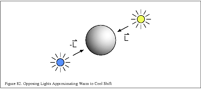
OpenGL lighting by using two opposed lights (![]() ,
, ![]() )
as shown in Figure 82.
The diffuse colors are set to
)
as shown in Figure 82.
The diffuse colors are set to
![]() ,
and
,
and
![]() , respectively, and the
ambient color set to (
, respectively, and the
ambient color set to (
![]() and the
specular and emissive contributions set to zero. Objects are drawn
with the material reflectances set to one (white). Highlights can
be added in a subsequent pass using blending to accumulate the
result. Alternatively the environment mapping techniques discussed
in Section 10.4 can be used to capture and apply
the BRDF at the expensive of computing a map for each
different object material.
and the
specular and emissive contributions set to zero. Objects are drawn
with the material reflectances set to one (white). Highlights can
be added in a subsequent pass using blending to accumulate the
result. Alternatively the environment mapping techniques discussed
in Section 10.4 can be used to capture and apply
the BRDF at the expensive of computing a map for each
different object material.

For metallic surfaces, the lighting model is further augmented
to simulate the appearance of anisotropic reflection (Section 10.9).
While anisotropic reflection typically occurs on machined (milled) metal parts
rather than polished parts, the anisotropic model is used
to provide a cue that the surfaces are metal and to provide
a sense of curvature. To simulate the anisotropic reflection
pattern, the curved surface is shaded with stripes along the
parametric axis of maximum curvature. The intensity of
the stripes are random values between 0.0 and 0.5, except
the stripe closest to the light source is set to 1.0 to
simulate a highlight. The values between the stripes are
interpolated. This process is implemented in the OpenGL
pipeline using texture mapping. A small one- or two-dimensional
luminance texture is created containing the randomized set of
stripe values. The stripe at ![]() coordinate zero (or some
well known position) is set to the value one. The object is drawn
with texture enabled and the wrap mode set to GL_ CLAMP and the
coordinate zero (or some
well known position) is set to the value one. The object is drawn
with texture enabled and the wrap mode set to GL_ CLAMP and the
![]() texture coordinate set to vary along the curvature. The position of the
highlight is adjusted by biasing the
texture coordinate set to vary along the curvature. The position of the
highlight is adjusted by biasing the ![]() coordinate with
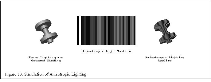
the texture matrix. This procedure is illustrated in Figure 83.
coordinate with
the texture matrix. This procedure is illustrated in Figure 83.
