Currently, OpenGL only provides an isotropic filter for texture minification.
This means that the amount of filtering done along the ![]() and
and ![]() axes of the
texture is the same, and is the maximum of the filtering needed along each
of the two axes individually. This can lead to excessive blurring when a
texture is viewed at any angle other than straight on. If it is
known that a texture will always be viewed at a given angle or range of
angles, it can be created in a way that reduces over-filtering.
axes of the
texture is the same, and is the maximum of the filtering needed along each
of the two axes individually. This can lead to excessive blurring when a
texture is viewed at any angle other than straight on. If it is
known that a texture will always be viewed at a given angle or range of
angles, it can be created in a way that reduces over-filtering.

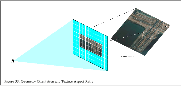
Suppose a textured square is rendered as shown in the left of
Figure 31. The texture is shown in the right.
Consider the fragment that is shaded dark. Its ideal footprint is shown
in the diagram of the texture as the dark inner region. But
since the minification filter is isotropic, the actual footprint is forced to
a square that encloses the dark region. A mipmap level will be chosen in which
this square footprint is properly filtered for the fragment; in other words, a
mipmap level will be selected in which the size of this square is closest
to the size of the fragment. That mipmap is not level zero but level 1 or
higher. Hence, at that fragment more filtering is needed along ![]() than
along
than
along ![]() , but the same amount of filtering is done in both. The result will
be that the texture will be blurred more than it needs to be.
, but the same amount of filtering is done in both. The result will
be that the texture will be blurred more than it needs to be.

To avoid this problem, do the extra filtering along ![]() when
you create the texture, and make the texture have the same width but only half
the height. See Figure 31. The footprint now has an aspect
ratio that is more square, so the enclosing square is not much larger, and is
closer to the size to the fragment. Level 0 will be used instead of a higher
level. Another way to think about this is that by using a texture that is
shorter along
when
you create the texture, and make the texture have the same width but only half
the height. See Figure 31. The footprint now has an aspect
ratio that is more square, so the enclosing square is not much larger, and is
closer to the size to the fragment. Level 0 will be used instead of a higher
level. Another way to think about this is that by using a texture that is
shorter along ![]() , you reduce the amount of minification that is required
along
, you reduce the amount of minification that is required
along ![]() .
.
The closer the filtered mipmaps aspect ratio matches the projected aspect ratio of the geometry, the more accurate the sampling will be. An application can minimize excessive blurring at the expense of texture memory by creating a set of re-sampled mipmaps with different aspect ratios.
The application can choose the mipmap that most closely corresponds to the texture scaling ratio being applied to the textured terrain. This ratio can be quickly estimated by computing the angle between the viewers line of sight and a plane representing the terrains average orientation. Using texture objects, the application can switch to the mipmap will provide the best results.

Since texture levels must have power of two dimensions, it would appear that
the only aspect ratios that can be prefiltered are 1:4, 1:2, 1:1, 2:1, 4:1,
etc. You can actually define smaller aspect ratio step size by using a
combination of incomplete texture images and use of the texture transform
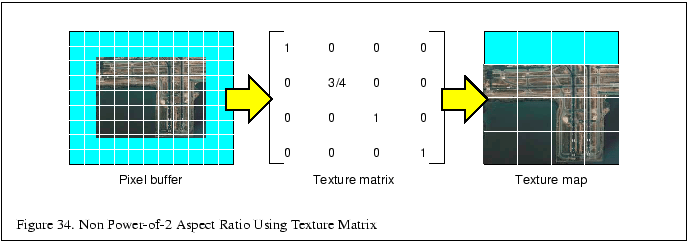
matrix. For example, say you want a ratio of 3:4. You cannot define a mipmap
with lengths of this ratio, but you can define a 1:1 ratio mipmap and define
an image that is scaled into a 3:4 ratio within it. The part of the texture
that is not used should be placed along the top (maximum ![]() coordinates) or
right (maximum
coordinates) or
right (maximum ![]() coordinates) edge of the texture image. The scaled image
can be any size, as long as it fits within the texture level. You can then
create a mipmap in the normal way.
coordinates) edge of the texture image. The scaled image
can be any size, as long as it fits within the texture level. You can then
create a mipmap in the normal way.
Using this mipmap for some textured geometry with a 3:4
ratio, results in an incorrect textured image. Be sure to set the
texture transform matrix to rescale the narrower side of the texture (in
our example in the ![]() direction) by 3/4:
direction) by 3/4:

This will change the apparent size ratio between the pixels and textures in
the texture filtering system, giving you the proper results. This technique
would not work well with a wrapped texture; in our example, there is a
discontinuity in the image when you filter outside the range of ![]() to
to ![]() in
in ![]() . However, in our example, wrapping in
. However, in our example, wrapping in ![]() would work fine.
would work fine.